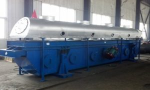
Fluidized bed dryer
 Relying on the powerful technical strength, we can customized calculate and design the equipments according to the detailed material condition and requirements from customers. Make sure the equipments most suitable to the users.
Working Principle:
Two equipped vibrating motors on the dryer produce exciting force, which makes materials leap forward along the horizontal orifice plate. Hot air gets through orifice plate upward from the lower part, passes through the material layer to achieve the purpose of dehydration.
Feature:
- Energy efficient. As material leaps around though orifice plate and fully contacts with the hot air, thermal efficiency is very high.
- Widely used. Changing of vibrating motor exciting force and installation direction angle can change material’s running speed and running status, so it’s suitable for drying or cooling different kinds of materials.
- Good drying effect. Vibration makes material in leaping status, hot air from lower part may have a damping effect, so material wear less, it’s broken rate is low, and no overheating or leakage phenomenon.
- Low noise, good vibration isolating. The equipment can be put on the floor slab directly, installed and removed conveniently, and sealed well, creating a nice working condition.
- If partition is set up in the middle of container, with hot air in the front section, and cold air in the back section, drying and cooling can be achieved simultaneously.
- Low investment, low operating cost, simple in structure, sturdy and durable, easy maintenance, light weight.
- Automatic material feeding device can be installed to realize feeding evenly and continuously, constitute an automatic flow production line.Application:
Foodstuff, chemical industry, pharmaceutical industry, feedstuff, plastic, salt manufacture, grain, seed, cigarette, sugar, metallurgy etc.
Main technical parameter:
| Length of dryer (mm) | Width of vibration container
(mm) |
Width of dryer (mm) | Height of dryer
(mm) |
Weight
(kg) |
| 3000 | 300 | 1350 | 1700 | 1240 |
| 600 | 1650 | 1700 | 1400 | |
| 900 | 1950 | 1850 | 1630 | |
| 1200 | 2250 | 2050 | 2030 | |
| 1500 | 2650 | 2250 | 2420 | |
| 4500 | 300 | 1350 | 1700 | 1570 |
| 600 | 1650 | 1700 | 1860 | |
| 900 | 2000 | 1850 | 2430 | |
| 1200 | 2300 | 2050 | 3030 | |
| 1500 | 2600 | 2250 | 3680 | |
| 6000 | 500 | 1350 | 1700 | 1960 |
| 600 | 1700 | 1700 | 2440 | |
| 900 | 2000 | 1850 | 3160 | |
| 1200 | 2400 | 2050 | 3580 | |
| 1500 | 2700 | 2250 | 4230 | |
| 7500 | 600 | 1700 | 1700 | 3900 |
| 900 | 2100 | 1850 | 4140 | |
| 1200 | 2500 | 2040 | 5190 | |
| 1500 | 2950 | 2450 | 5940 |
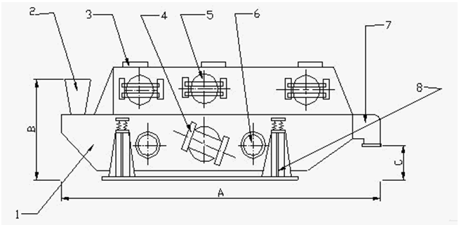
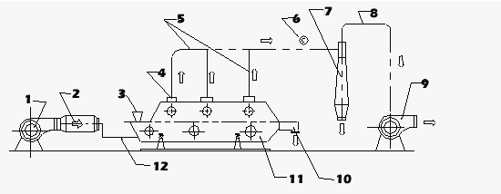
Structure diagram:

1.Dryer 2. Feeding inlet 3.Air outlet 4.Vibration motor
5.Cleaning peep door 6.Air inlet 7.Discharging outlet 8.Rack

1.blower 2.heater 3.charging machine 4.flexible pipe 5.exhaust pipe
6.thermometer(2 pieces) 7.dust precipitator 8.exhaust pipe 9.exhaust fan
10.discharging outlet 11.drying device 12.air supplying pipe

